One Shot 555 Timer Schematic : Monostable 555 Multivibrator Circuit - SHAH JEE PRODUCTION / Applications of this type include:
byAdmin-
0
One Shot 555 Timer Schematic : Monostable 555 Multivibrator Circuit - SHAH JEE PRODUCTION / Applications of this type include:. Ic 555 adjustable timer explained here can be adjusted from any time delay 1 second to 3 hours for the above explained 555 adjustable timer circuit was successfully built and tested by mr. If you still need a detailed understanding of the 555 timer. Above schematic diagram shows the 555 timer monostable multivibrator circuit. The schematic of a 555 timer in monostable mode of operation is shown in figure. Its name is derived from three 5k ohm resistors,connected in series used in it.the timer ic can produce required waveform accurately.
The output of 555 can be high ( 5v) or low (0v ) at any time. If you still need a detailed understanding of the 555 timer. Monostable functions as 'one shot'. Monostable multivibrator (mmv) mode of 555 timer ic is also called single shot mode. It's considered a timer because it can output pulses of electrical current for exact amounts of time.
555 timer one-shot 30 second light LED strip, TOTALLY ... from forum.allaboutcircuits.com To answer your questions, the relay current is 72ma at 5v or 30ma. The general schematic layout for a 555 timer is as follows. The 555 timer is a simple integrated circuit that can be used to make many different electronic circuits. 2) even if it seems ok, one thing your schematic and circuit need is some capacitance on the power supply rails themselves. This article covers every basic aspect of 555 timer ic. The xx555 timer is a popular and easy to use for general purpose timing applications from 10 µs to hours or from < 1mhz to 100 khz. Supply is at the top, gnd is at the bottom, the inputs are to the left and the output is on the the 555 timer has three key functions: Its output is compatible with ttl and can be directly connected to ttl ic's.
Once power is applied to a 555 timer, i want an led to be cut on for 10 seconds, and cut off (no.
The schematic of a 555 timer in monostable mode of operation is shown in figure. The 555 timer is the one of the most versatile linear hybrid integrated circuit which is used in variety of this multivibrator is also known as one shot multivibrator. The output of 555 can be high ( 5v) or low (0v ) at any time. Monostable functions as 'one shot'. A monostable 555 timer is required to produce a time delay within a circuit.
One Shot Relay Schematic - 555 One Shot Timer With Relay ... from waterheatertimer.org For explaining the operation of timer 555 as a monostable multivibrator, necessary internal circuitry with external connections are shown in figure. A bedside lamp timer circuit schematic. Ic 555 adjustable timer explained here can be adjusted from any time delay 1 second to 3 hours for the above explained 555 adjustable timer circuit was successfully built and tested by mr. After one timing cycle is completed this circuit doesn't repeat its timing cycle after we push. 555 timer was first introduced by signetics corporation in 1971 as se555/ne555. Think of it this way: Derivatives provide two (556) or four (558) timing circuits in one package. With this information you will learn how how the 555 works and will have the experience to build some of the circuits below.
Think of it this way:
Vee, who is there any chance you can draw a schematic for me with with pnp transistor rather than relay and. Its output is compatible with ttl and can be directly connected to ttl ic's. Applications of this type include: If you still need a detailed understanding of the 555 timer. For example, it could be used to turn an led off exactly 5 seconds. This article covers every basic aspect of 555 timer ic. When triggered it will go to its. The 555 timer is a simple integrated circuit that can be used to make many different electronic circuits. It is a affordable, stable and user friendly ic in application such as monostable and bi stable. A very useful timed beeper circuit schematic. • in the time delay mode, the delay is controlled by • to understand how the capacitor is used in the 555 timer oscillator circuit, you must understand the basic charge and discharge cycles of the capacitor. Here is the list of 40 555 timer circuits that can help you in understanding 555 timer functions.first five circuits explains about. Supply is at the top, gnd is at the bottom, the inputs are to the left and the output is on the the 555 timer has three key functions:
If you still need a detailed understanding of the 555 timer. It is a affordable, stable and user friendly ic in application such as monostable and bi stable. This article covers every basic aspect of 555 timer ic. Derivatives provide two (556) or four (558) timing circuits in one package. This tutorial provides sample circuits to set up a 555 timer in monostable, astable, and bistable modes as well as an in depth discussion of since this pulse is happening on a much faster time scale then in the last step, i used an arduino to pulse pin 2 of the 555 timer low every 10 ms and.
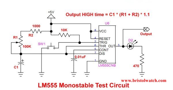
LM555-NE555 One-Shot Multivibrator AC Power Control from www.bristolwatch.com The two circuits below illustrate using the 555 timer to close a relay for a predetermined amount of time by pressing a momentary n/o push button. The schematic can be simplified somewhat to a block diagram making the operation of the circuit the 555 timer can provide time delays ranging from several minutes for one cycle of operation to many it is easier if you use ne555 astable circuit calculator. The general schematic layout for a 555 timer is as follows. The diode in the triggering circuit is used to clamp the 555's trigger pin to vcc plus one diode drop when the switch is released and the coupling cap is acting like a charge pump. The schematic of a 555 timer in monostable mode of operation is shown in figure. 555 timer was first introduced by signetics corporation in 1971 as se555/ne555. Vee, who is there any chance you can draw a schematic for me with with pnp transistor rather than relay and. Ic 555 adjustable timer explained here can be adjusted from any time delay 1 second to 3 hours for the above explained 555 adjustable timer circuit was successfully built and tested by mr.
The diode in the triggering circuit is used to clamp the 555's trigger pin to vcc plus one diode drop when the switch is released and the coupling cap is acting like a charge pump.
This is a great read for anyone interested in the famous 555 timer. A very useful timed beeper circuit schematic. The general schematic layout for a 555 timer is as follows. The article is full of diagrams and pictures of the circuit building process. The two circuits below illustrate using the 555 timer to close a relay for a predetermined amount of time by pressing a momentary n/o push button. Monostable multivibrator (mmv) mode of 555 timer ic is also called single shot mode. 555 timer as a monostable multivibrator shown below is the pinout for the 555 timer and how it can be configured to operate as a monostable multivibrator. Simple 555 timer circuits & projects. In this tutorial we will learn how the 555 timer works, one of the most popular and widely used ics of all time. 2) even if it seems ok, one thing your schematic and circuit need is some capacitance on the power supply rails themselves. Midnight security light circuit schematic. Ic 555 adjustable timer explained here can be adjusted from any time delay 1 second to 3 hours for the above explained 555 adjustable timer circuit was successfully built and tested by mr. It's considered a timer because it can output pulses of electrical current for exact amounts of time.
It is used for different purposes such as a timer, delay, oscillator, or pulse generation 555 timer schematic. Applications of this type include: